PanGazer – overlays
PanGazer uses ‘status’ text fields to show camera settings, etc. (see the settings page). In addition, it can overlay data on the image that are directly related to the image itself rather than being simply numerical data.
You can toggle on/off the display of all the overlay and status displays currently visible in a view using the Space Bar (or from the View or pop-up menus); this overrides individual settings.
Currently the following overlays are available (more details below):
- Grid – overlays a tilt and heading grid on all images (at 15° intervals on spherical images, variable for others); this will be aligned to the horizon and also to North (if known, otherwise aligned with the centre of the image). You can toggle the Grid overlay by pressing the ‘#’ (hash) key. For more details, see below and also the Grid overlay page.
- Tilt and heading angles – overlays tilt angles at the left of the view and heading angles at the top of the view. These will be aligned to the Horizon and/or North (as known, otherwise aligned with the centre of the image); they are different colours for clarity. Tilt and heading angles are always shown if the grid is overlaid.
- Compass points – if the bearing of the image is known (see Setting North), this overlays points of the compass across the top of the view to indicate the direction of view. These replace any overlaid heading angles. You can toggle between compass points and heading angles by pressing ‘@’.
- North line – if the bearing of the image is known (see Setting North) then the line along which all points are due North is overlaid.
- Horizon line – if the horizon of the image is known and is in view, this overlays a ‘zero tilt’ line; this will always be horizontal.
If the bearing or horizon is not known you can set it, as described below.
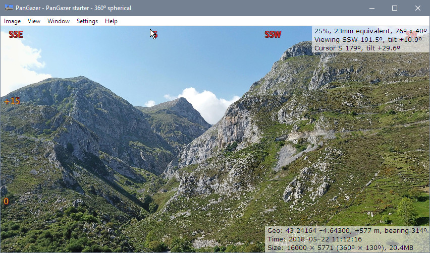
Here is a screenshot showing the Compass points and Tilt angles overlays (the same view showing the grid is shown below and in the grid overlay page):
Grid
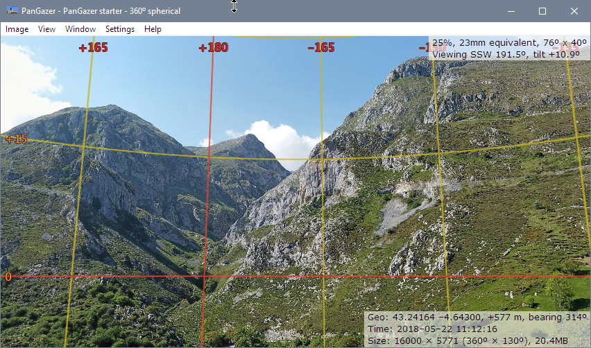
The grid is overlaid on images (at 15° intervals on spherical images, variable for others); this will be aligned to North and/or the Horizon (as known – see above and under ‘Tilt angle’ and ‘Heading angle’, below) or otherwise is aligned with the centre of the image. In either case, 90° lines are shown in a red and others in a yellow (see the image included in the grid overlay page)). Near the poles the grid lines are faded out so as not to obscure image detail.
You can turn the grid overlay off or on by clicking the Settings → Overlays → Show grid menu item, or by pressing ‘#’. If the grid is being overlaid then tilt and heading angles are also overlaid.
For more details, see the Grid overlay page.
Tilt angle
The tilt angle of the image is the vertical angle of the centre of the view relative to the horizon (positive is above the horizon) with a range from −90 through +90 degrees. For spherical images the position of the horizon is fixed and is calculated from the geometry of the image (the bottom edge of the image is at −90 degrees).
For all other images (360° or not) the image may include tilt information (if not it is assumed the image is not tilted), and in all cases you can set, edit, or delete the horizon position. There are two ways to set the horizon position:
- You can use the Image Geography dialog to set
(or delete) the tilt of the centre of the image.
- If the horizon is visible in the image, right-click on it and select Set horizon on the pop-up menu. You should then see the tilt angles at the left of the view. If their position is wrong, just try again (or use the Image Geography dialog to adjust or delete the value).
Tilt angles are calculated at the point where the overlay is displayed; this will match the Grid if it is being overlaid.
The tilt angles are overlaid if the grid is overlaid or if the Settings → Overlays → Show tilt and heading angles menu item is selected.
Heading angle
Similar to the tilt angle, the heading angle is the horizontal angle of the centre of the view relative to the centre of the image (or relative to North, if known). See the Setting North page for more details.
The heading angles are overlaid if the grid is overlaid or if the Settings → Overlays → Show tilt and heading angles menu item is selected.
Heading angles are calculated at the point where the overlay is displayed; this will match the Grid if it is being overlaid.
Compass points
PanGazer lets you set where North is for any image. Once North is set, as detailed on the Setting North page, PanGazer can show the bearing of the cursor and can also overlay compass points (‘N’, ‘S’, ‘SW’, etc.) at the top of the view to help give a sense of direction – as shown in the screenshot above.
The overlaid compass points change to match the view as you change viewpoint and zoom. You can turn them off or on by clicking the Settings → Overlays → Show compass points menu item. If this is checked and North is set then compass points will be shown even if other overlays are not selected.
Some images (such as those from 360° cameras) include a North setting; if these are not identified as True North PanGazer will still use them but add a ‘?’ to the bearing in status displays. In all cases you can override the image North by Setting North explicitly.
The view bearing (or heading angle) is calculated at the position that the compass points are displayed (near the top of the view rather than at the centre point of the view). This is so the bearings remain static relative to the displayed image as the view is changed.
If North is not known then heading angles relative to the centre of the image are shown if the grid is overlaid.
North line
The North line is shown if North is set and the Settings → Overlays → Show North line menu item is selected. It is also implied if the Grid is overlaid (it is identical to the north line in the grid).
Horizon line
The Horizon line is shown if the Horizon is known and the Settings → Overlays → Show Horizon line menu item is selected. It is also implied if the Grid is overlaid (it is identical to the horizon line in the grid).
Here is a screenshot showing the Heading and Tilt angles overlays together with the Grid overlay:
Notes:
- Once the North point or horizon has been set it will be recorded
in the image file (in its Exif metadata, and in XMP metadata too
if the image is spherical) if the image is saved (using Ctrl-s, Ctrl-r,
or Image → Save image as..., etc.). When it is next loaded
the bearing and/or horizon of the image is known and compass points
and tilt and heading angles will be shown automatically if set to
be shown.
- Similarly, if you save a view of an image that has its North
point and/or horizon set, that saved view will include known geographic
settings with appropriately adjusted photographic parameters; see
the Saving views page for more details.
- In the starter image you’ll see a white electricity pylon close to the −90° point if you tilt down far enough; the base of the pylon is close to True North from the drone position.

