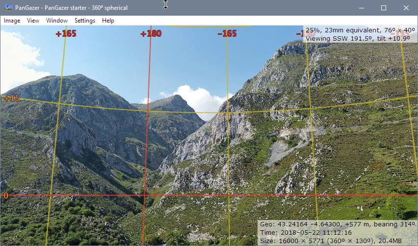
PanGazer – grid overlay
The PanGazer grid overlays a grid (at 15° intervals on spherical images, variable for others) that shows all points of the same heading or tilt in any image, which helps to visualise the field of view. The grid will be aligned to the Horizon and/or North (as known, or otherwise is aligned with the centre of the image).
You can turn the grid overlay off or on by clicking the Settings → Overlays → Show grid menu item, or by pressing ‘#’. If the grid is being overlaid then tilt and heading angles are also overlaid; you can choose to overlay compass points instead of heading angles (bearings), if North has been set. You can toggle between compass points and heading angles by pressing ‘@’.
Grid 90° lines are shown in a red and others in a yellow (see image below). Near the poles the grid lines are faded out so as not to obscure image detail.
If the image has lens metadata (its focal length is known) the grid will be rectilinear and will exactly match the grid from a spherical image zoomed to that focal length. Here is an example (showing bearings as angles instead of compass points):
Depending of the known attitude of the image (e.g., the tilt and bearing of a camera, if recorded in the metadata) the grid will be adjusted to allow for this.
More specifically:
- For spherical images, the horizon is always known and the tilt is therefore calculated using the horizon as zero. If North is known then the heading grid lines are bearings, calculated using North as zero. Bearings can be shown and angles or compass points, toggled by pressing ‘@’.
- For images with lens metadata, the tilt angles will be relative to the vertical centre of the image adjusted to match the camera tilt if known. North is used as for spherical images.
- For all other (‘flat’) images, the grid is rectangular and will use the centre of the image as zero for both heading and tilt. Images that wrap in X (cylindrical) are 360° and therefore heading degrees are known. For other flat images an assumed diagonal angle of view of 54° is used for calculating the grid spacing.
Notes:
- When a view is saved the new image will have correctly
adjusted focal length, bearing, and tilt; this means that PanGazer
can add the grid overlay correctly, and this will exactly match the
original image grid. This is because PanGazer uses the same code
for both: spherical images also use the rectilinear gnomonic projection.
- Three keyboard shortcuts are especially useful when working with
grids:
- Press ‘#’ to toggle the Show grid overlay on and off.
- Press ‘@’ to toggle between compass points and heading angles.
- Press the Space Bar to toggle all overlays and status on and off (to view the image without anything obscuring it).
- When overlaying a grid on images with lens metadata PanGazer assumes the image is rectilinear (because most are and there as no way to detect when this is not the case). This means that the grid will be incorrect for images taken with (for example) a fisheye lens.
