Requires: GPS, optional accelerometers
This application was built to experiment with aircraft attitude display derived from GPS information and accelerometers.
Accelerometers cannot be used for deducing aircraft bank angle in the air because in a coordinated turn “down” is always at right angles to the wings; however, the attitude of the aircraft can be calculated from the rate of turn of the aircraft – and this can be determined from GPS readings.
GPS readings also have the advantage of being an external reference, so there is no dead-reckoning drift. There is necessarily a lag (delay) in calculating the bank angle; however, for just checking that the aircraft is flying straight with wings level this would not seem to be a major problem. It would be interesting to have an experienced instrument-rated pilot evaluate this.
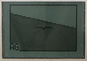
The picture shown was taken in flight; in this case, accelerometer data is merged with the GPS-derived bank to show aircraft pitch and allow for any slip. Other GPS data (the ground speed, altitude, bearing, etc., shown in the GPS summary) could be added to the display for a miniature “glass cockpit”.
Theory & practice
This application uses the same accelerometer data (smoothed over 8 readings) as the slip ball application. The primary data, however, comes from GPS, using the change of course (ground track bearing) over one second (currently using instantaneous bearings – experiments are in progress to use calculated bearings, or fitting circles or ellipses to GPS fixes, which could give a more accurate estimate with less lag).
The key equations governing a turning aircraft in flight are as follows:
turn radius, r = v2 / (9.81 × tan(b))
rate of turn, ω = (g × tan(b)) / v
centripetal acceleration, ca = v2/ r = ω2× r (m/s2)
where
v = tangential velocity (m/s) (= kts × 0.514)
r = radius of the turn (m)
ω = angular velocity (rads/s) (= degrees/sec × π/180 = degrees/sec × 0.01745)
b = bank angle (in degrees if tan function takes degrees)
v=ω × r, hence
ca=ω × v and r=v/ω [verifiable from first principles]
Hence bank angle, b, is such that
tan(b) = ca/g
= ω × v / g
The load factor (total acceleration), lf = sqrt(g2 + ca2) = 1 / cos(b)
(so the bank angle could in theory be calculated from accelerometer data, though not its direction – except perhaps by dead reckoning from initial uncoordinated movements)
Hence the bank angle can be determined from the centripetal acceleration, which is the turn rate times the velocity. However, the centripetal acceleration can be used directly to draw the graphic (there is no need to calculate the angle).
When first trying this I was surprised to see that the calculated bank was steeper than the actual bank of the aircraft (for example, 40° calculated when the horizon was at 30°) – in other words, the aircraft was turning more tightly than would be predicted from the physical bank angle. This was confirmed by inspecting the GPS ground track for a 360° turn (on a calm day) – the radius of the turn was similarly smaller than expected for the amount of bank applied. Happily, this effect errs on the safe side – the instrument shows a steeper bank than the real attitude of the aircraft.
I presume this effect is due to differential drag on the airframe during the turn; it seems very constant (it is not noticeably affected by slip in an uncoordinated turn, or by moderate climb or descent, or by whether the turn is to the right or to the left). The software therefore currently applies a fixed adjustment (70%) to the calculated centripetal acceleration, and this gives a displayed bank angle that closely matches reality over a range of turns. This adjustment might well need to be a calibration setting for other aircraft (these experiments were carried on in an Ikarus C42).
Pitch is (optionally) added to the display using accelerometer readings. When switched off the display only shows roll. The accelerometer-derived pitch will be wrong when ‘pulling up’, etc., but seems helpful in normal flight.
Lag and delay
The lag and delay in the roll axis probably will determine whether this ‘Pilot assist’ is useful. There are several sources of lag and delay in the system:
- The ‘black box’ software in the GPS device. This reports a new
(ground track) compass bearing every 100 ms – but there are no details
available of how that is calculated.
It should be using Kalman filtering and
so on, but almost certainly has a delay/lag involved.
- I calculate the rate of turn by comparing the bearing (true course)
‘now’ with
the bearing one second earlier – so this would report the
average rate of turn over the past second. If one is in a
tightening turn this would be lower than the current rate. If
one is levelling out then it would be higher than the current
rate. In a coordinated steady turn it would be the current rate.
The effective delay/lag caused by this will be from 0 to 0.5
seconds (generally rather less than 0.5 I would think).
- There is a delay since the last GPS data were received and ‘now’.
This will be between 0 to 0.1 seconds.
- There is some computation time needed to process the GPS sentences and draw the screen. At the moment that is 10–15 ms.
(1) and (2) are the tricky ones. (1) because it is an unknown, and (2) because it depends not on the rate of turn but on the rate of change of the rate of turn. (i.e., the roll rate).
Accelerometer data alone
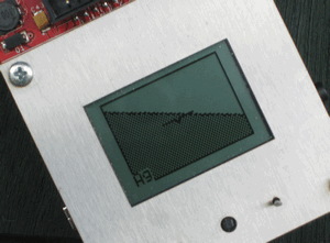
The picture to the right shows the device on the ground, with no GPS fix. Here the “bank angle” is simply derived from the accelerometer data.For experimental purposes the joystick can be used to select GPS data, accelerometer data, or a blend of the two. Use of the accelerometer data alone was useful for testing the drawing calculations (one can rotate the device around the z axis and the ‘horizon’ will stay level, with the dark ‘earth’ below, in all positions).
Alternative display layouts are also selected using the joystick; either a square display or the same rectangular one without a border. This choice would probably be better made using a configuration menu.
