The GPS module I attached to the Starter Kit is the Locosys LS20031 » smart antenna. This includes:
- Mediatek MT3329 interface chip »
- serial interface
- up to 10Hz data refresh rate
- fix indicator LED.
This is driven from the processor’s USART2 interface, available at the board’s UEXT connector. Four wires make the connection. Note that this module communicates using the following settings:
- 115200 baud for the 10Hz device
(slower LS20031 devices use different baud rates: the 1Hz device uses 9600 baud and the 5Hz device uses 57600 baud.)
- 8 data bits, 1 stop bit, no parity
- no hardware flow control
Once initialized, program-selected NMEA sentences are sent from the device to the processor at regular intervals, up to 10Hz. I used the interrupt capabilities of the driver to handle each incoming byte. When a complete sentence is available, and checked, then the main application is notified. A ring of five buffers is used to handle up to five monitored sentences.
Currently, I am using 10Hz for course/position information, with slower (1Hz) updates for data such as quality of signal.
Attachment
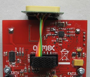
Only four wires are needed to attach the GPS module to the device (power, ground, Rx, Tx), as seen in the picture. Mechanical attachment is effected by ‘Velcro’ patches.Power requirement
GPS modules are relatively ‘expensive’ in their power requirements. This one draws 35 mA at 3.3 V, and this is roughly constant regardless of how frequently messages are sent to the microcontroller.This is a significant proportion (70%) of the total power drain when the gadget is running off battery power and showing the most complex display (the Pilot assist application).
