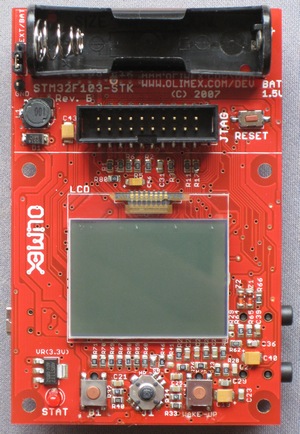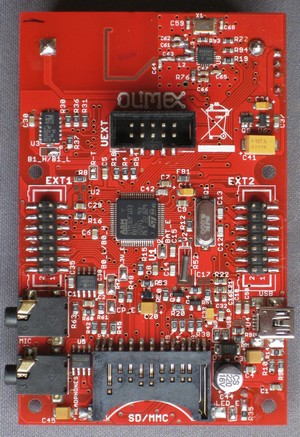
The Olimex STM32-103STK Starter Kit » currently used for my experiments is a development board which is essentially a complete computer. To this I added only:
- a GPS module
- extensions to the push buttons (clipped-off round-headed nails) to allow them to be operated without a stylus.
The development board includes the following peripherals:
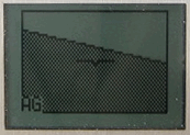
- NOKIA 3310 » monochrome reflective display (84×48 pixels)
- two user buttons and a joystick (4 directions + push); also a reset button and status LED
- 3-axis accelerometer
- SD-MMC card adapter and socket
- audio input and output
- 2.4 GHz radio transceiver using the Nordic nRF24L01 chipset
- USB and JTAG connectors for power and debugging when connected to a PC
- UEXT connector for attaching other peripherals (I used this to attach the GPS module)
- extension headers for all other processor ports.
The microcontroller (in the centre of the picture of the rear of the board) is an ST Microelectronics STM32F103RBT6 » ARM CORTEX M3™. This includes:
- the 32-bit 72 MHz (90 DMIPS) processor core
- 128KBytes Program Flash memory
- 20KBytes RAM
- USB, CAN, two I2C bus, and two SPI drivers
- two 12-bit ADC converters
- three USART drivers
- seven timers (PWM, watchdog, etc.)
- JTAG & SWD debug interfaces.
Other components include:
- the 1.5V AA battery connector with step-up converter (the controller and other components require 3.3V)
- an 8 Mhz crystal oscillator
- a 32768 Hz crystal and Real-Time-Clock backup battery connector.
All of the above are mounted on a PCB which is 90 × 65mm (3.5 × 2.5″); the whole weighs 116g (including AA battery and GPS module).
For more details, see the Olimex page shown above, which includes the starter kit documentation ».
Board front guide
The front view of the board shows (from top to bottom):- AA battery holder
- JTAG debug connector and reset button
- LCD (display) assembly
- Red LED, pushbutton, joystick, and pushbutton.
Board rear guide
The rear view of the board shows (from top to bottom):- 2.4 GHz radio antenna and transceiver
- Accelerometers chip and UEXT connector
- Connector, ARM Cortex chip, crystals, connector
- Microphone jack, amplifier chip, USB connector
- Headphones jack, amplifier chip, SD/MMC connector.

