More pictures
Timeline & people
Documentation
Firmware
Schematics
Specifications
Emulator Overview
Using the Monitor
Emulator Menus
Mini-Debugger

|

|

|

|
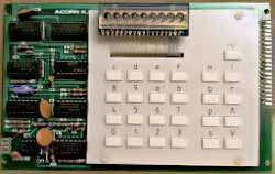
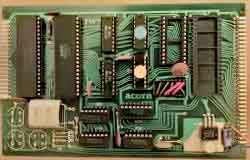
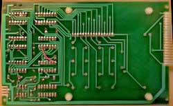
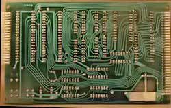
When assembled, the 20-way ribbon cable seen leaving at the top right of the Keyboard is led between the two boards and connects to the Microcomputer board at top left.
Footnote: All the photographs on this site (as opposed to the scanned images) were taken with a Canon G1 digital camera. In order to achieve maximum resolution under poor lighting, close-ups using the macro mode were used – hence the barrel distortion; apologies for that! Many thanks for Fabio Arpino for post-processsing them to correct some of that.